Forklift Stability

The project aims to understand the practical application of statics equations in real-life engineering examples.

14

0

Cover Image

introduction

The Forklift Stability project entails determining the load capacity that a forklift can withstand while remaining stable. This project requires a thorough understanding of the various factors that can influence forklift stability, such as load weight, load distribution, forklift height, and operating speed. The project intends to analyze these factors in order to determine the maximum safe load capacity of a forklift and to develop strategies for maintaining stability while carrying loads. The project's ultimate goal is to ensure the safety of forklift operators and those working in close proximity to forklifts.

Task Set-up

Case Study
Forklift self-weight:Ms = 2600 [kg]Lowering speed:Vs = 0.5 [m/s]
Forklift load capacity:Mt = 1400 [kg]Lowering braking distance:S = 20 [mm]
Force on the front wheel without load:Fe = 5000 [N]Distance between the front axle and fork face:C = 0.40 [m]
Force on the rear wheel without load:Fh = 7753 [N]Load position:X = 0.50 [m]
Total mass of the moving parts:Mm = 160 [kg]Wheelbase:L = 1.30 [m]

Calculate the value of static stability factor (π‘˜ =?)

The condition for longitudinal stability (the tilting moment must be less than the stabilizing moment) in other word the the moment of the forklift has to be more than the moment of the load around the fixed A point.

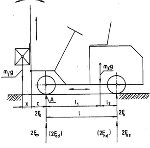
From observing the image we could obtain the following the equation:

mtβ‹…gβ‹…(c+x)<msβ‹…gβ‹…l1mt\cdot g\cdot \left(c+x\right)<ms\cdot g\cdot l1

Introducing the static stability factor (k>1), the range which will allow is to equalize the equation and can increase or decrease both of the load position and load capacity based on.

kβ‹…mtβ‹…β€…gβ‹…(c+x)<β€…msβ‹…β€…gβ‹…β€…l1k\cdot mt\cdot \:g\cdot \left(c+x\right)<\:ms\cdot \:g\cdot \:l1
kβ€…=β€…msβ‹…β€…l1mtβ‹…β€…(c+x)k\:=\:\frac{ms\cdot \:l1}{mt\cdot \:\left(c+x\right)}
kβ€…=β€…2600β‹…β€…0.791400β‹…β€…(0.4+0.5)β€…=β€…1.63k\:=\:\frac{2600\cdot \:0.79}{1400\cdot \:\left(0.4+0.5\right)}\:=\:1.63

where;

Calculating the l1 by determining the moment around point A of the unloaded forklift.

βˆ‘MAβ€…=β€…2Fhβ‹…lβˆ’msβ‹…gβ‹…l1β€…=β€…0β€…β€…\sum MA{\:=\:2Fh\cdot l-ms\cdot g\cdot l1\:=\:0}\:\:
l1β€…=β€…2Fhβ‹…lmsβ‹…gl1\:=\:\frac{2Fh\cdot l}{ms\cdot g}
l1β€…=β€…2β‹…7753β‹…1.302600β‹…9.81β€…=β€…0.79[m]l1\:=\:\frac{2\cdot 7753\cdot 1.30}{2600\cdot 9.81}\:=\:0.79\left[m\right]

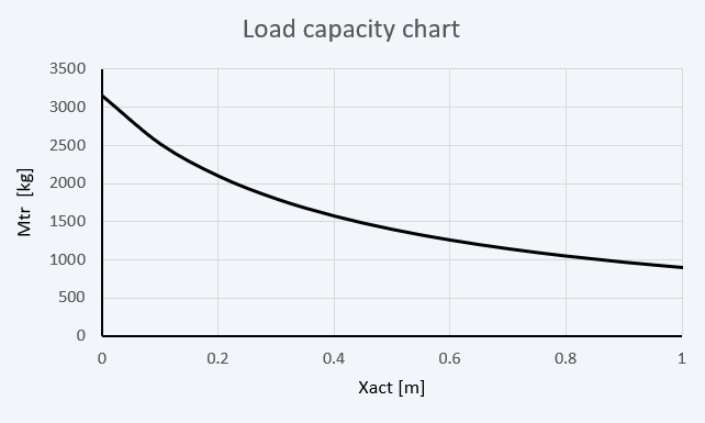
Load capacity chart (load capacity vs. load position diagram)

Applying the previous equation of the stability and knowing ( k ) is fixed. If the actual position of mass center( xact ) change from it original ( x ) with all other remain constant that will lead to change of ( mt ) forklift load capacity to a new value ( mtr ).

mtrβ€…=β€…msβ‹…l1kβ‹…(c+xact)mtr\:=\:\frac{ms\cdot l1}{k\cdot \left(c+xact\right)}
For different x value:
Xact [m]00.10.20.30.40.50.60.70.80.91.0
Mtr [kg]3150.32520.221001800.11575.11400.112601145.61050.1969.3900.1

so,

Calculate static forces on the wheels with max. load (𝐹hs =?, 𝐹es =?)

Calculating the statics force on rear wheels can be done by the help of using the law of static equilibrium for moment around point ( A ) thus we will get 3 forces.

βˆ‘(Ma)β€…=β€…mtβ‹…gβ‹…(c+x)+2Fhsβ‹…lβˆ’msβ‹…gβ‹…l1=0\sum \left(Ma\right)\:=\:mt\cdot g\cdot \left(c+x\right)+2Fhs\cdot l-ms\cdot g\cdot l1=0
Fhsβ€…=β€…msβ‹…gβ‹…l1βˆ’mtβ‹…gβ‹…(c+x)2β‹…lFhs\:=\:\frac{ms\cdot g\cdot l1-mt\cdot g\cdot \left(c+x\right)}{2\cdot l}
Fhsβ€…=β€…2600β‹…9.81β‹…0.79βˆ’1400β‹…9.81β‹…(0.4+0.5)2β‹…1.3β€…=β€…2995.8β€…[N]Fhs\:=\:\frac{2600\cdot 9.81\cdot 0.79-1400\cdot 9.81\cdot \left(0.4+0.5\right)}{2\cdot 1.3}\:=\:2995.8\:\left[N\right]

By the help of newton 4th law we can calculate the static force on the front wheels.

βˆ‘(Fy)β€…=β€…βˆ’mtβ‹…gβˆ’msβ‹…g+2β‹…Fesβ€…+2β‹…Fhsβ€…=β€…0\sum \left(Fy\right)\:=\:-mt\cdot g-ms\cdot g+2\cdot Fes\:+2\cdot Fhs\:=\:0
Fesβ€…=β€…mtβ‹…β€…g+msβ‹…β€…gβˆ’2β‹…Fhs2Fes\:=\:\frac{mt\cdot \:g+ms\cdot \:g-2\cdot Fhs}{2}
Fesβ€…=β€…1400β‹…β€…9.81+2600β‹…9.81β‹…β€…2β‹…2995.82β€…=β€…16624.2β€…[N]Fes\:=\:\frac{1400\cdot \:9.81+2600\cdot 9.81\cdot \:2\cdot 2995.8}{2}\:=\:16624.2\:\left[N\right]

Calculate dynamic forces on the wheels under braking of the max. load (𝐹hd =?, 𝐹ed =?)

The dynamic force on rear wheels.

Fhdβ€…=β€…msβ‹…gβ‹…l1βˆ’(mtβ‹…g+F1)β‹…(c+x)2β‹…lFhd\:=\:\frac{ms\cdot g\cdot l1-\left(mt\cdot g+F1\right)\cdot \left(c+x\right)}{2\cdot l}
Fhdβ€…=β€…2600β‹…9.81β‹…0.79βˆ’(1400β‹…9.81+9750)β‹…(0.4+0.5)2β‹…1.3=βˆ’379[N]Fhd\:=\:\frac{2600\cdot 9.81\cdot 0.79-\left(1400\cdot 9.81+9750\right)\cdot \left(0.4+0.5\right)}{2\cdot 1.3}=-379\left[N\right]

Where:

  • The sum of moving masses during lowering the load.
Msumβ€…=β€…mt+mmMsum\:=\:mt+mm
Msumβ€…=β€…1400+160=1560β€…[kg]Msum\:=\:1400+160=1560\:\left[kg\right]
  • The kinetic energy of moving masses.
Ekβ€…=β€…Msumβ€…β‹…Vs22Ek\:=\:\frac{Msum\:\cdot Vs^2}{2}
Ekβ€…=β€…1560β€…β‹…0.522β€…=β€…195β€…[J]Ek\:=\:\frac{1560\:\cdot 0.5^2}{2}\:=\:195\:\left[J\right]
  • Assuming constant de-acceleration applying 2nd law of newton.
F1β€…=β€…EksF1\:=\:\frac{Ek}{s}
F1β€…=β€…19520β‹…10βˆ’3β€…=β€…9750β€…[N]F1\:=\:\frac{195}{20\cdot 10^{-3}}\:=\:9750\:\left[N\right]

So, The dynamic force on the front wheels.

Fedβ€…=β€…mtβ‹…g+F1+msβ‹…gβˆ’2β‹…Fhd2Fed\:=\:\frac{mt\cdot g+F1+ms\cdot g-2\cdot Fhd}{2}
Fedβ€…=β€…1400β‹…9.81+9750+2600β‹…9.81βˆ’2β‹…βˆ’3792β€…=β€…24874β€…[N]Fed\:=\:\frac{1400\cdot 9.81+9750+2600\cdot 9.81-2\cdot -379}{2}\:=\:24874\:\left[N\right]

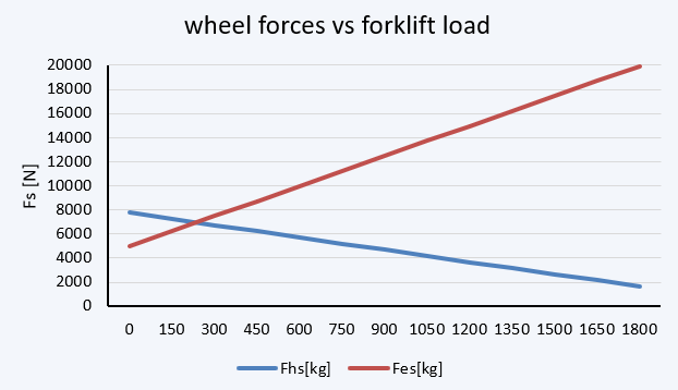
A wheel forces vs. forklift load diagram

The relation between the static wheel forces and the forklift load
m [kg]0150300450600750900105012001350150016501800
Fhs [N]7750724067316222571252034694418436753166265621471638
Fes [N]500362487493873899841122912474137191496416209174541869919945

discussion

We established a K safety factor value as the base for further static investigations. Through these investigations, we were able to identify all the forces applied to the forklift structure and generate a load capacity diagram. This diagram provides a reference for determining the maximum load capacity for different centers of loaded mass and enables us to push the forklift's load capacity to its limits. We also determined the range of distributed forces on both the rear and front wheels for different forklift load capacities.

conclusion

Finally, this project can help students understand how statics equations can be used to solve real-world engineering problems. It can also highlight the importance of accuracy and precision in calculations, as well as the importance of taking into account real-world factors when using statics equations.