Verification of the Kirchhoff’s laws
Fares Al Rwaihy
April 15, 2023
147
1
This series of blog posts aims to compare the hand calculation and numerical simulation techniques through technical software
2 min read
Introduction:
Kirchhoff's laws are fundamental principles of electrical circuit analysis that are widely used in various fields of engineering. These laws are essential for designing and analyzing complex electrical circuits. Kirchhoff's current law (Node) and Kirchhoff's voltage law (Mesh) are two of the most important laws in circuit theory, which govern the behavior of electric circuits.
Objective:
The main objective of this project is to verify the validity of Kirchhoff's laws by comparing the results of a hand calculation with a NI Multisim simulation.
Verification of the Kirchhoff’s laws
Ni Multisim results:
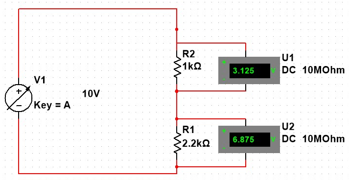
In this experiment we would like to show the verification of the Kirchhoff’s junction (node) and loop (mesh) laws by calculation and measurement.
We can show in the first experiment that the difference voltage splits between each resistance, where we can find both of the differences of voltage that equal to the supply voltage. We set a voltmeter to show the difference in voltage as it pass a resistance
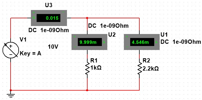
On the second experiment we show that the currents splits between each node, So the sum ofthe total current splits equal to the beginning current. We set a Ammeter to show the current changes as the current pass into a nodes.
Hand Calculation results:
First we need to illustrate the equations of Parallel and Series electric circuit
Series VS Parallel.
in Series:
in Parallel:
For the First experiment results
So,
For the Second experiment results, we know, as illustrated in the previous sections, about Parallel circuits
So,