Enhancing Manufacturing Efficiency: Exploring GD&T
Fares Al Rwaihy
May 24, 2023
70
1
Discover the power of Geometric Dimensioning and Tolerancing (GD&T) in optimizing manufacturing efficiency.
5 min read
Introduction
In our previous post about enhancing manufacturing efficiency, we delved into Design for Manufacturability (DFM) and Design for Assembly (DFA). Continuing in the same vein, this post will focus on another essential aspect of manufacturing: Geometric Dimensioning and Tolerancing (GD&T). GD&T is a symbolic language used to communicate design requirements for geometric features on mechanical parts and assemblies.
Benefits
Tolerances and GD&T are used to make sure that parts are made correctly and fit together properly. They help ensure product quality, compatibility, and efficient manufacturing. By specifying tolerances, engineers set acceptable limits for dimensions and features. This ensures parts work well together, can be easily interchanged, and are made efficiently. GD&T helps designers communicate their intentions clearly, and it helps manufacturers understand and meet those requirements. Tolerances and GD&T also guide inspection and quality control processes to ensure parts meet the desired specifications. Overall, they help create reliable and well-designed products.
Datum Reference
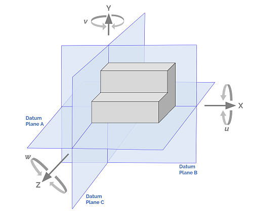
In GD&T, there are three key terms related to datums:
- Datum Feature: A datum feature refers to a physical feature on a part that is identified as a datum. These features, such as flat surfaces, holes, or cylindrical surfaces, serve as reference points or planes for dimensional control.
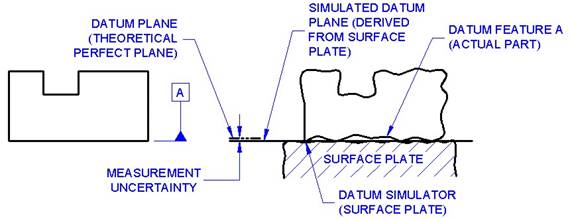
- Datum Simulator: A datum simulator is a device or fixture used during inspection to simulate a perfect or theoretical datum feature. It provides a reference for verifying the geometric relationships of other features on the part.
- Datum Theoretical: Datum theoretical is a term used to describe the perfect or ideal representation of a datum feature. It represents the intended form, size, and orientation of the datum feature without considering any manufacturing or assembly variations.
These terms are important in GD&T as they help establish a consistent reference system and enable accurate dimensional control and interpretation of part drawings.
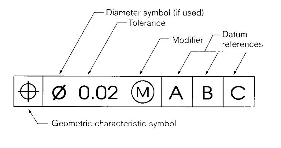
Geometric characteristics symbols
**Thanks to redlux and keyence for the great demonstration of such a solution.
Form Controls
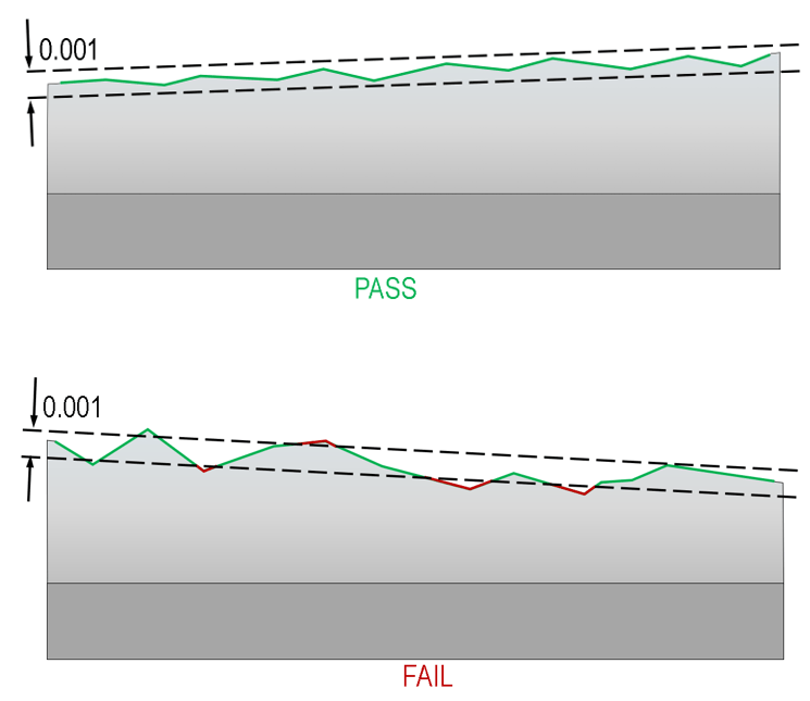
- Straightness: Indicates the deviation of a feature from a perfectly straight line.
Showing the geometry with the tolerance condition
We can then illustrate the tolerance range
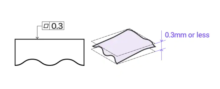
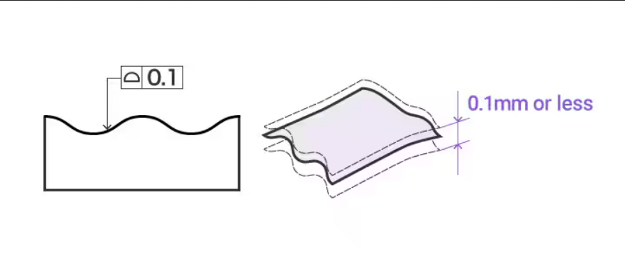
- Flatness: Specifies the allowable deviation from a perfectly flat surface.
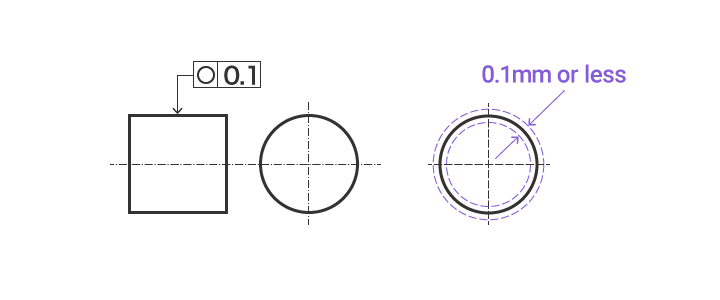
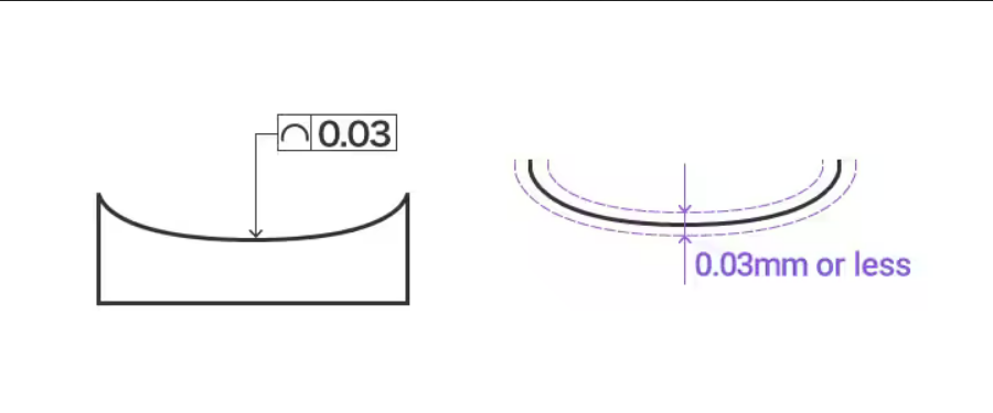
- Circularity: Defines the tolerance for circular features such as cylinders or holes.
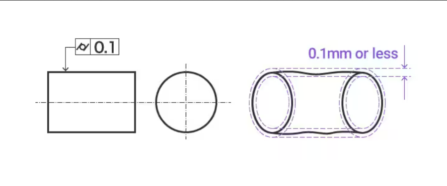
- Cylindricity: Specifies the allowable variation in form of a cylindrical feature.
Profile Controls
- Profile of a Line: Measures 1D profile deviation from ideal design. Controls form and location. Used for edges, slots, or curves.
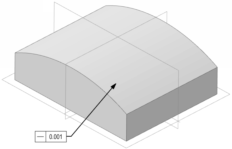
- Profile of a Surface: Measures 2D surface deviation from ideal design. Controls form and orientation. Used for flanges, sealing surfaces, or complex curves.
Orientation Controls
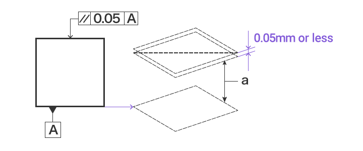
- Parallelism: Indicates the permissible degree of non-parallelism between two surfaces or axes.
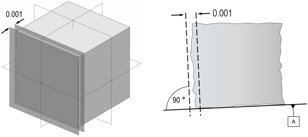
- Perpendicularity: Specifies the allowable deviation from a 90-degree angle between two surfaces or axes.
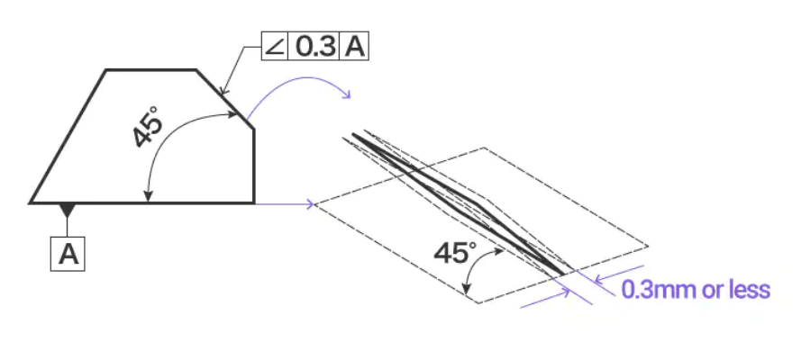
- Angularity: Defines the permissible variation from a specified angle.
Location Controls
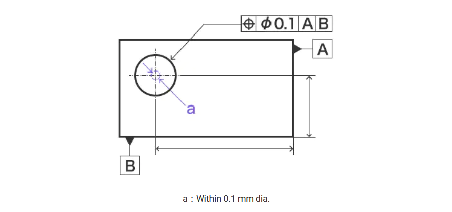
- Position: Specifies the permissible location of a feature relative to a reference.
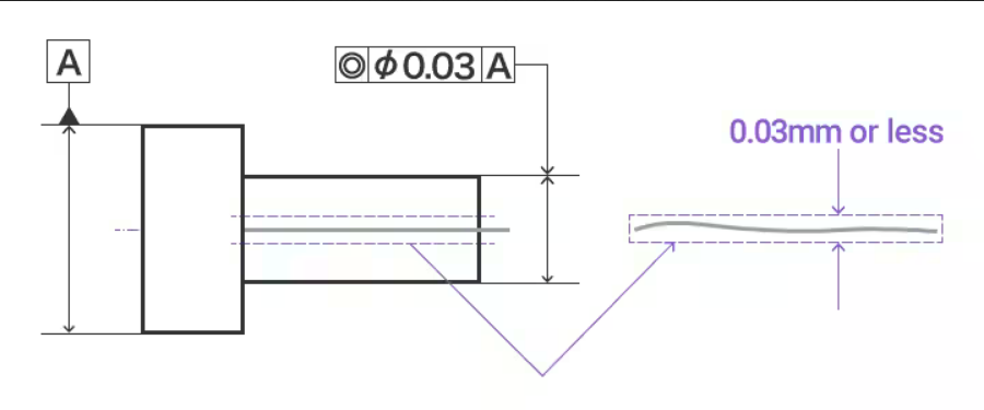
- Concentricity: Indicates the allowable deviation between two features, such as a cylinder within another cylinder.
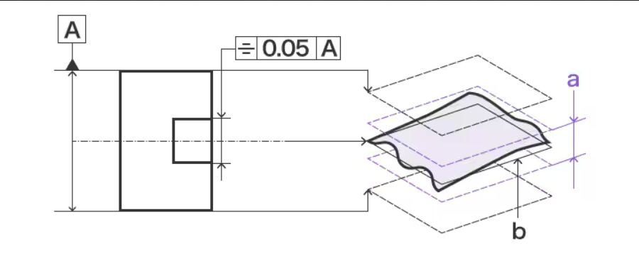
- Symmetry: Defines the acceptable deviation of a feature from its perfect symmetry.
Runout Controls:
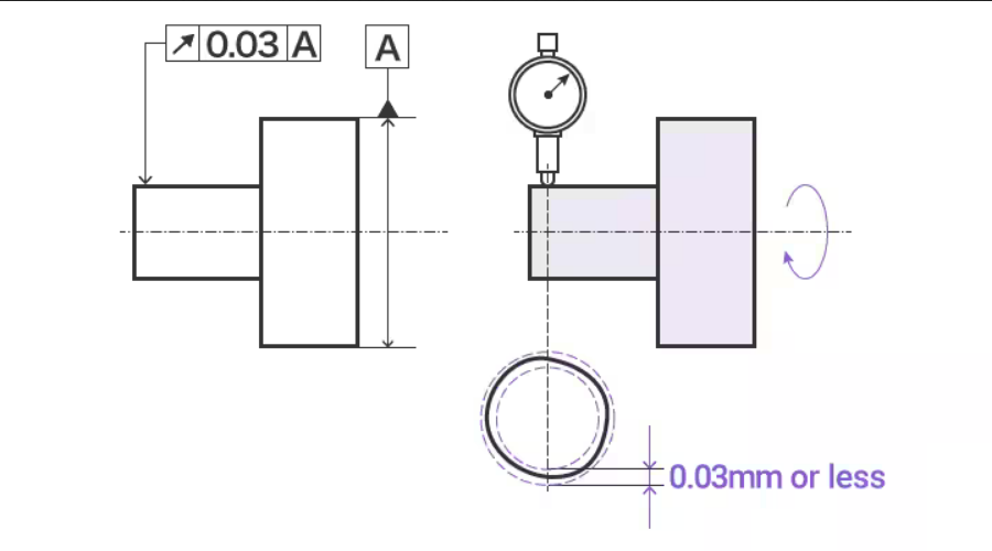
- Circular Runout: Specifies the acceptable variation in circular features, such as a rotating shaft.
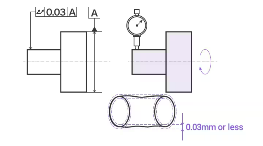
- Total Runout: Indicates the permissible deviation of a feature along its entire length.
Applicable Standards
GD&T follows specific standards to ensure consistent interpretation and communication. The widely recognized standards are:
- ASME Y14.5: Developed by the American Society of Mechanical Engineers (ASME), this standard is commonly used in North America.
- ISO 1101: Published by the International Organization for Standardization (ISO), this standard is used globally.